69.85 mm controlled Rev E body depth.
POWER, WITHOUT THE OBJECT
THE ROOMKEEPS ITSCOMPOSURE.
A patent-pending mechanical concept designed to place the charger and cord below the finished surface.
CONCEPT VISUALIZATIONREV E NON-ENERGIZED MECHANICAL PROTOTYPE
01
Finish-matched lid02
Charger storage below03
Separate service zone
Finish-matched lid02
Charger storage below03
Separate service zone
A DIFFERENT KIND OF FLOOR POWER
Most outlets add something to a room. This one gives something back.
The uninterrupted floor.
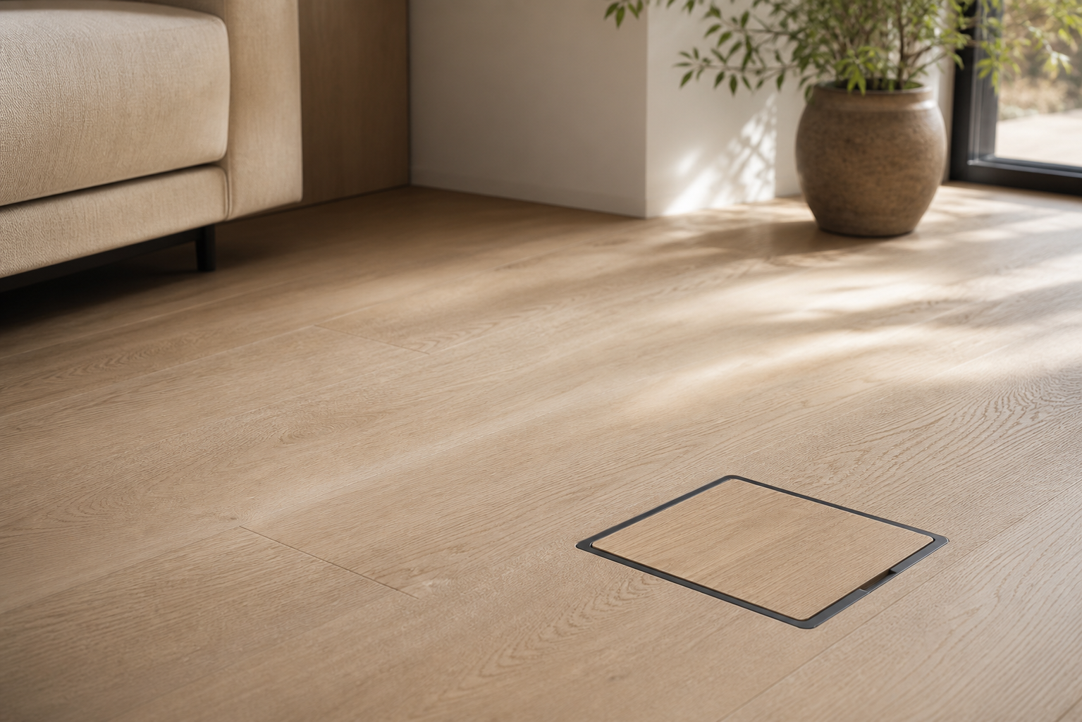
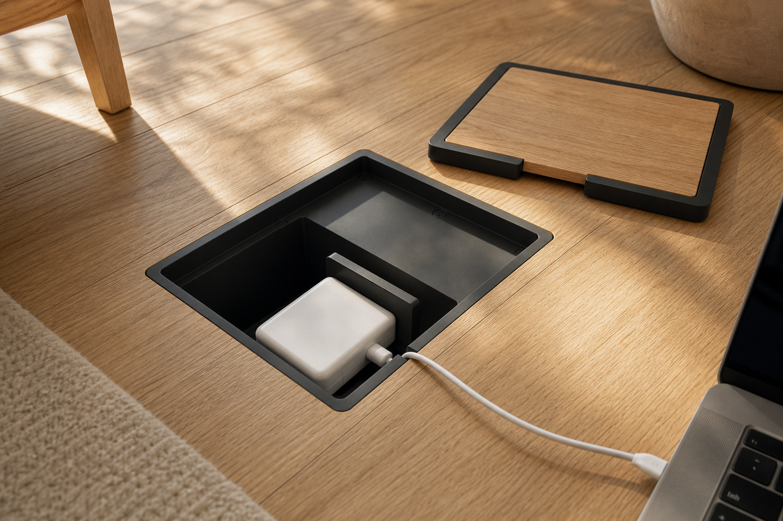
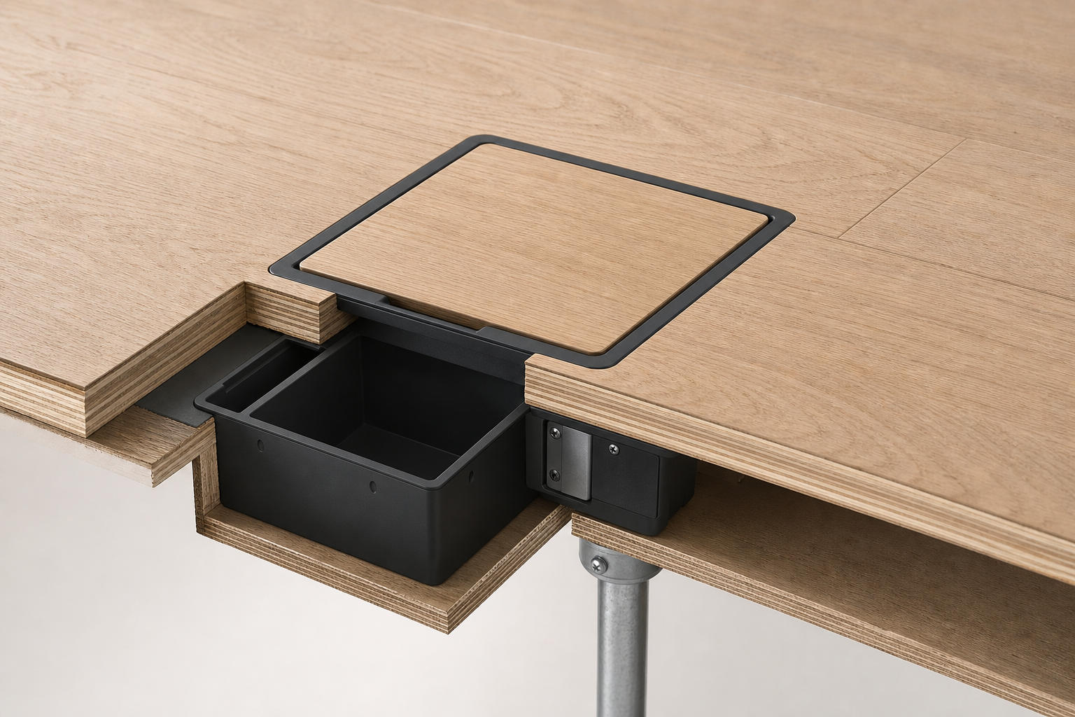
CONCEPT VISUALIZATION NOT A PHOTOGRAPH OF A FINISHED OR LISTED PRODUCT
01 / CLOSEDFirst, it
First, it
vanishes.
Design intent: carry the surrounding finish so the eye reads one continuous floor.
02 / IN USEThen, the mess
Then, the mess
goes with it.
Design intent: store the adapter and excess cable below while the working cord reaches the room.
03 / BENEATHShallow
Shallow
by design.
In the Rev E CAD architecture, storage and the service sidecar sit beside one another within a 2.750 in nominal depth.
115.37 × 83.62 mm opening in the nominal CAD model.
Calculated stack-up target—not a measured production tolerance.
REV E / SOURCE OF TRUTH
What CAD controls.
What is still concept.
Geometry below comes from the controlled Rev E dimension CSV, stack-up JSON, and CAD source. Photoreal materials, room scenes, colors, shadows, and final production appearance are illustrative.
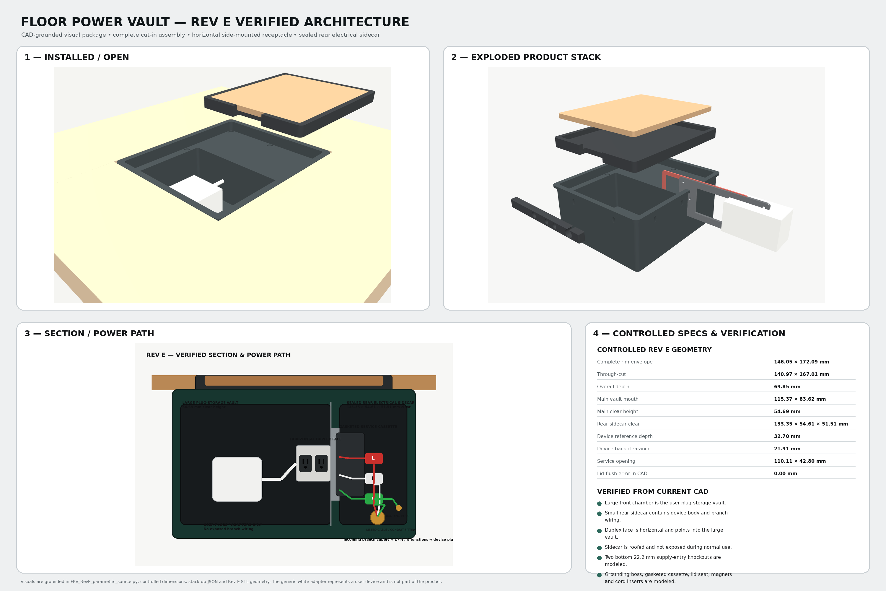
CONTROLLED NOMINAL GEOMETRYREV E / 2026-07-15
- Complete rim envelope
- 5.750 × 6.775 in 146.050 × 172.085 mm
- Body outer size
- 5.500 × 6.525 in 139.700 × 165.735 mm
- Overall depth
- 2.750 in 69.85 mm
- Through-cut target
- 5.550 × 6.575 in 140.970 × 167.005 mm
- Flush-rabbet target
- 5.780 × 6.805 × 0.130 in deep 146.812 × 172.847 × 3.302 mm
- Main storage mouth
- ≈ 4.54 × 3.29 in 115.37 × 83.62 mm
- Main clear height
- ≈ 2.153 in 54.69 mm
- Lid / finish insert
- 0.472 / 0.236 in 11.989 / 5.994 mm
- Service cassette
- 4.650 × 2.000 × 0.118 in 118.11 × 50.80 × 2.997 mm
- Device depth / modeled clearance
- 1.287 / 0.863 in 32.70 / 21.91 mm
CAD-CONTROLLED Nominal dimensions and component architecture.
ILLUSTRATIVE Materials, finishes, lighting, rooms, and rendered transitions.
NOT YET VALIDATED Physical tolerances, loads, spill resistance, thermal behavior, listing, and field installation.
REV E ARCHITECTURE / CONCEPT FILM
Take it apart.
Build it back.
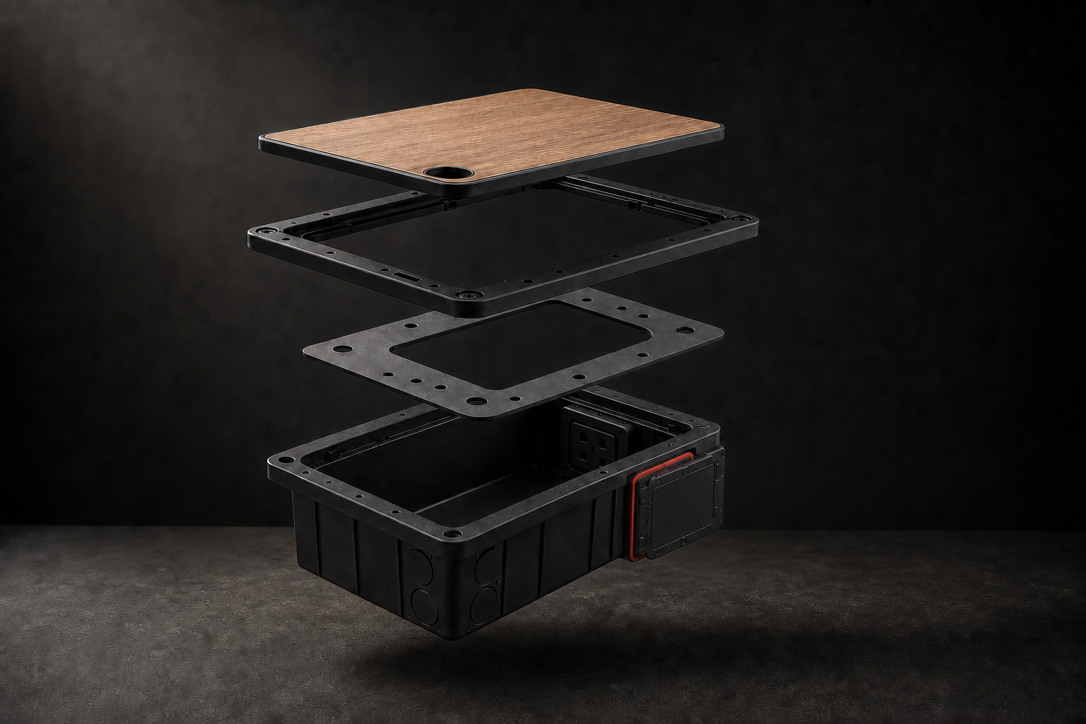
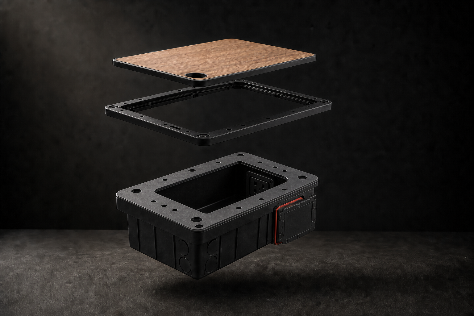
The assembly sequence follows the Rev E architecture, but the photoreal frames are illustrative and not dimensionally controlling. The CAD ledger above governs.
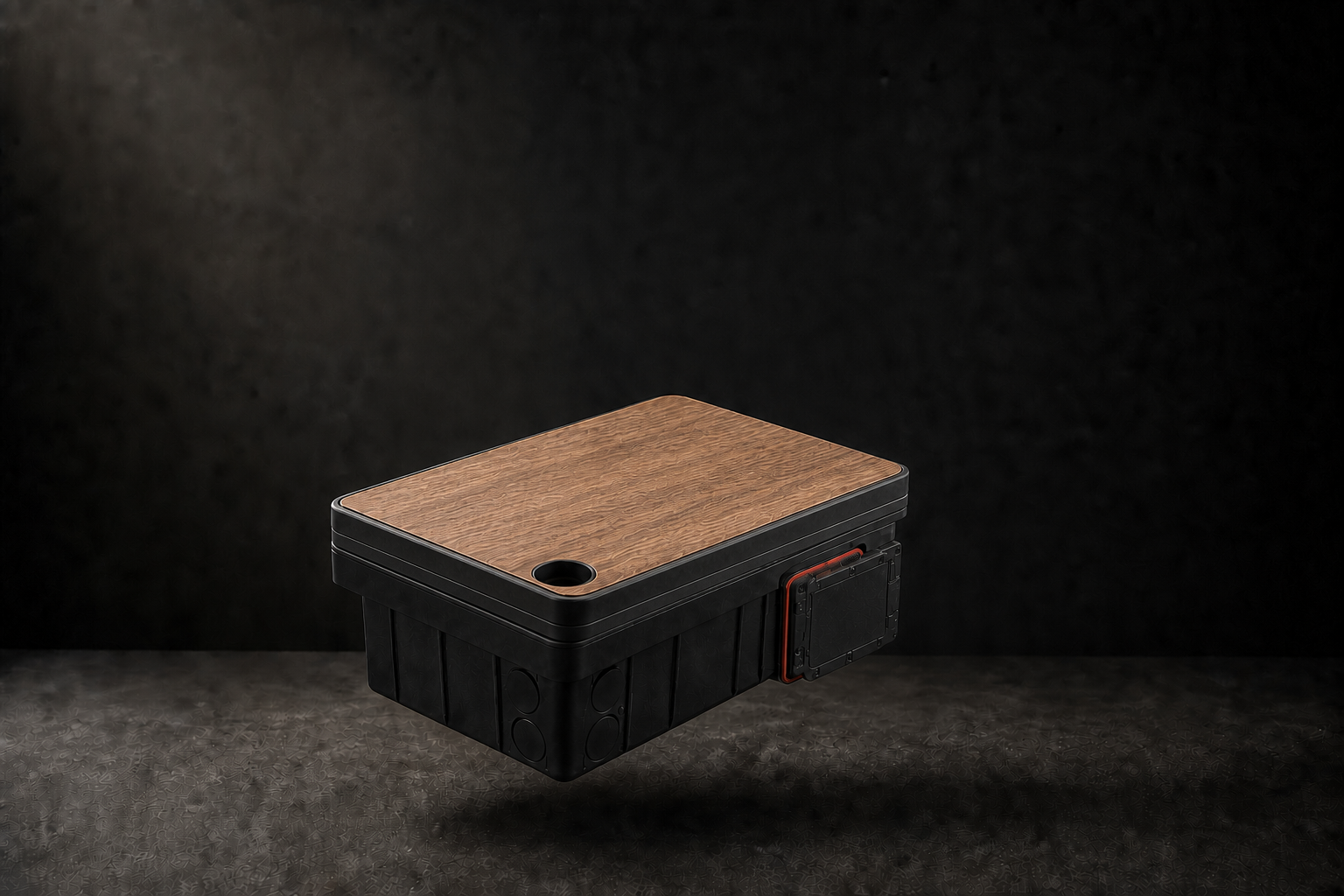
CONCEPT VISUALIZATION CAD DIMENSIONS GOVERN
ASSEMBLY STATE000%
ILLUSTRATIVE REV E / LOCKED CAMERA + LIGHT
REV E / CINEMATIC ASSEMBLYFULLY EXPLODED
- 01Interior receptacle
The duplex device docks on the right interior service wall, facing into the storage vault.
- 02Adapter plate
The precision plate seats on the structural vault and establishes the final assembly plane.
- 03Magnet-pocket carrier
The carrier lowers into the nominal Rev E lid seat above the storage volume.
- 04Finish insert
The illustrative oak insert settles into the carrier at the nominal CAD flush plane.
CORE SYSTEM / CONCEPT RENDER
Key parts.
Architecture exposed.
ILLUSTRATIVE APPEARANCE / CAD GOVERNS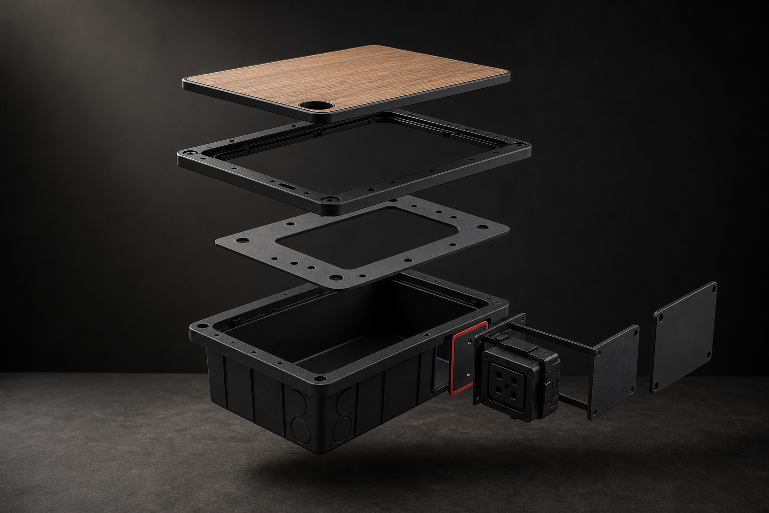 01 WHITE-OAK FINISH02 MAGNETIC CARRIER03 SHALLOW STORAGE VAULT04 GASKET + SERVICE CASSETTE
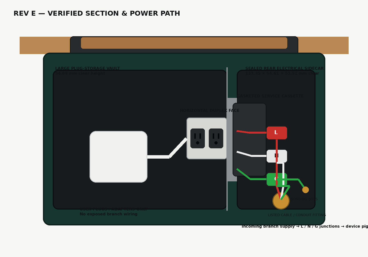
01 WHITE-OAK FINISH02 MAGNETIC CARRIER03 SHALLOW STORAGE VAULT04 GASKET + SERVICE CASSETTEThis is the architecture—not a decorative cover over an ordinary floor box. The adapter lives in a clean user vault while the receptacle and branch wiring remain next door in a removable service plane.
USER STORAGEELECTRICAL SERVICE
THE POWER PATH
Power beside.
Storage below.
Separating the everyday cavity from the electrical service area is what keeps the profile shallow and the charger out of sight.
FROM SUBFLOOR TO SILENCE
Five moves.
One clean plane.
CONCEPTUAL INSTALLATION SEQUENCE — NOT FIELD INSTRUCTIONS — REQUIRES PRODUCT CERTIFICATION, LICENSED DESIGN REVIEW, AND AHJ APPROVAL
- 01PLAN
Find the clear bay.
Survey structure and services below. Verify the routing template before the first cut.
- 02PREP
Create the flush seat.
Cut the through-opening, then route the shallow perimeter ledge for the integral rim.
- 03PLACE
Set the vault.
In the proposed method, a final specified gasket would be fitted before the body is lowered and secured.
- 04POWER
Connect the sidecar.
After certification, a qualified electrician terminates and closes the gasketed service cassette.
- 05FINISH
Return the floor.
Test the assembly, verify cord clearance, and install the selected finish insert.
PROTOTYPE ≠ PRODUCT
The current printed assembly validates geometry only. It is not safety-listed and must not be installed or energized.
STOCK MATERIAL DIRECTIONS
The lid is
the room.
Four workable hardwood directions plus black polymer and solid brass. No stone, tile, terrazzo, or cement fabrication is being proposed.
01 / WOODWhite oakRift-sawn hardwood blank
02 / WOODAmerican walnutDark hardwood blank
03 / WOODHard mapleLight closed-grain hardwood
04 / WOODAmerican cherryWarm fine-grain hardwood
05 / STOCKBlack polymerMolded or machined cap
06 / STOCKSolid brassMachined sheet or plate
ILLUSTRATIVE MATERIAL DIRECTIONS / FINAL THICKNESS + FASTENING REQUIRE ENGINEERING
REV E / INTERIOR DIGITAL-TWIN LAB
Leave the room.
Enter the vault.
The camera crosses the finish plane, descends into the nominal 2.750-inch box, and parks at the inward-facing device bay. Every AC study now shows hot, neutral, and equipment-ground contacts—and every candidate carries an honest fit status.
LOADING CONTROLLED CAD
NOMINAL REV E ENCLOSURE DEVICE FIT SHOWN INDIVIDUALLY
LIVE SEQUENCETHE FLOOR / UNINTERRUPTED
5.750 × 6.775 IN2.750 IN DEEP
HELP MOVE REV E FORWARD
Power belongs
everywhere.
Outlets don't.
Floor Power Vault is in prototype development. Follow the journey through engineering validation, safety listing, and manufacturing.
I want to follow the build